

They were probably removed from old hard drives long time ago, and were lying in my parts drawer. I was considering buying 4-wire motors for my project, but I spotted this blog post, and decided to give it a try. Post gives 6-wire unipolar motor as an example, but rule presented can be applied to my motors as well.
Unipolar stepper motors come in at least 2 variations:
- 5-wire - center taps of both windings are soldered together internally
- 6-wire - center taps are available on the connector
6-wire motor gives easy access to side taps. 5-wire requires some fiddly soldering skills, and motor disassembly.
It's good to take ohm-meter and test windings before doing any soldering work. This will confirm type of motor, and winding condition.
In my case all windings showed around 75ohm.
Getting inside TEAC motors is very easy since there are 4 bolts holding back cover. Most often case is held with welded or pressed joints (like SANYO one).

Wires should be unsoldered, and separated.
There are 2 ways winding pairs can be soldered together. Unfortunately there is no way of telling witch is good. In my case first try was incorrect. Motor will oscillate instead of rotating when soldered incorrectly.
After soldering wires were secured with insulation tape.

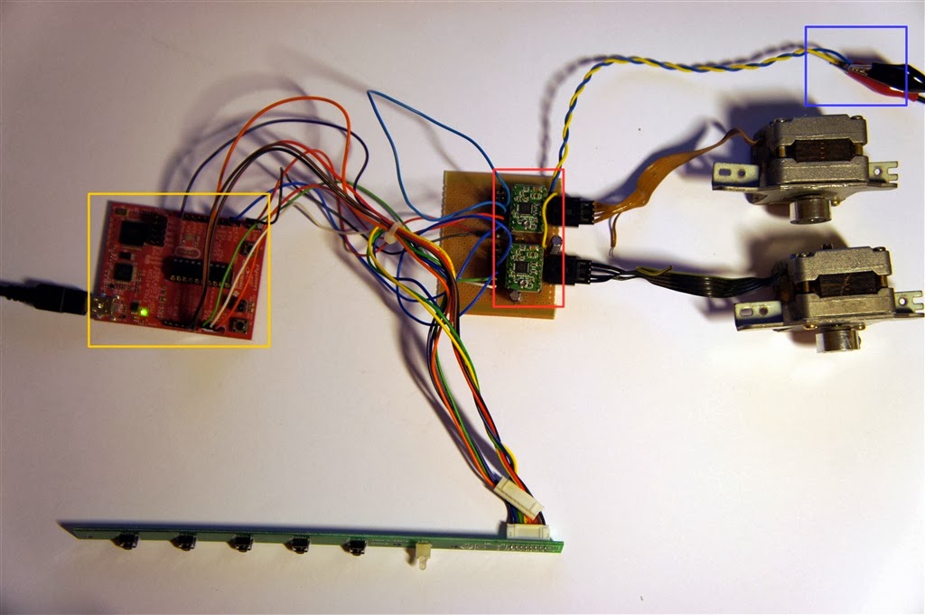
Then everything was assembled, and here is my test setup:
- MSP430G2 Launchpad board
- Two A4988 motor drivers configured for 1/2 step resolution
- External power supply for motors.
Video of motor operation:
Just for curiosity, here is disassembled view of SANYO motor that was actually destroyed in process.

Software started from TI stepper motor driver demo that can be downloaded here. Code for this project can be cloned from github.
Code can be imported to TI CCS workspace (tested with version 5.3.0).
Update (2015/12/07):
Pictures of motor resoldering are not clear enough, and I decided to add schematics below to help understanding.
Left schematic shows motor before conversion - there are 4 windings, that all have one end soldered together with others, and going out as single wire (connector may not be drew exactly to the motor specification, pin 1 corresponds to uppermost wire in the pictures). All four winding ends labeld 2, 3, 6, 7, are spliced together, and soldered to wire 1.
Right picture shows motor after conversion. So wire splice is unsoldered, and untangled. I identify phase windings by trial and error, and solder each pair together (2-3, and 6-7) effectively making 2 windings.
Let me know if this explanations is better.